NGFWE - 1.1 Interface Configuration
Overview
We’re going to move through this section pretty quickly. This post covers basic configuration and usage of the major interface types. Layer 2 and Layer 3 are the most common interface types and the choice to use either mainly comes down to what the adjacent devices are. The trickiest part about these is where to apply the VLAN.
1. Layer 2 and VLAN interfaces
Layer 2 interfaces can be configured to accept either tagged or untagged VLAN traffic. Palo Alto makes this a little difficult because they have two VLAN concepts:
- VLAN interface -
(Network > Interfaces > VLAN)Gets a tag and defines a tagged VLAN. Any interfaces grouped with it will only pass traffic with the tag defined here. - VLAN object -
(Network > VLANs)The VLAN object does not define the VLAN tag, it is only a logical container object for interfaces.
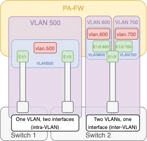
If you’re familiar with traditional Route/Switch devices, you’re probably familiar with access and trunk ports. Access ports assign a VLAN tag to incoming traffic, while trunk ports only pass traffic with the matching VLAN tags. In Palo Alto land, if you’re receiving tagged traffic on an L2 interface (i.e. over a trunk with multiple VLANs), you’ll need to perform the following steps:
- Configure a VLAN interface (tag, Virtual/Logical Router, Zone) - Only needed if you want an IP address for this VLAN on the firewall.
- Configure a VLAN object (I like to name mine VLAN<ID> so I know which VLAN it’s attached to at a glance)
- Configure your parent interface (Type, Security Zone, VLAN container for untagged traffic if needed.)
- Add a Subinterface
- Assign the tag for the VLAN you’re interested in. Make sure this doesn’t conflict with the tag defined on Step 1 if you configured one.
- Assign the subinterface to your VLAN container object
- Assign a L2 Security Zone to the subinterface. This will come into play if your source and destination interfaces on the firewall are both L2 and both on the same VLAN. Otherwise, for inter-VLAN traffic, the L3 zone on the VLAN interface will apply.
- Repeat for each VLAN on the trunk.
If you want to pass untagged traffic to a tagged VLAN, you’ll be able to use the parent interface directly. Just assign it to the VLAN container with the appropriate VLAN interface.
2. Layer 3
Layer 3 interfaces are pretty straightforward, and they’re by far the most common interface type (especially for on-prem firewalls).
- Configure the interface
(Network > Interfaces > Interface<ID>) - Set type to L3, and assign a router and zone
- Assign an IP address
If you want to be able to ping or access management on the interface, you’ll need to add a Management Profile under the “Advanced” tab in interface configuration. This is also where you can manage the MTU/MSS if needed.
The Link State (interface up/down) is set to auto by default, so it’ll come active as soon as the configuration is pushed. If you want to leave it off while you work on other things, make sure you set this to down.
l3-diagram.png to come3. Virtual Wire
Virtual wires are just what they sound like. These interfaces are created in pairs and must be assigned to a Vwire object (Network > Virtual Wires). Any traffic that enters one interface will exit through the other with no routing or switching performed. You can still assign security zones and do inspection on this traffic, but V-Wire is a specific zone type, so you can’t mix it with a L2 or L3 zone. This is a useful feature when you are implementing a new firewall and don’t want to change the network setup. The firewall in V-Wire mode can just be dropped in the middle like a bump in the wire. Configuration summary:
- Create vwire object
- Create vwire zones
- Create 2 vwire interfaces and assign them to the vwire object
vwire-diagram.png to come4. Tap
Tap interfaces are used to collect network data and do Threat Detection (not Prevention, think IDS not IPS if you’re familiar with those concepts, we’ll talk more about them later). If you have a device spanning traffic out a particular interface, this can be used to monitor traffic for suspicious activity, but it can’t be blocked or dropped because the traffic isn’t passing through the firewall in this case, just inspected. Configuration Summary:
- Set interface type to tap
- (Optional) Assign interface to security zone. It must be a Tap security zone type.
tap-diagram.png to come4. Tunnel Interfaces
Tunnel interfaces are another rather nuanced interface type, but they’re typically not too bad. They’re used to terminate IPSec and GRE tunnels, as well as for some applications of GlobalProtect (although that’s generally just to terminate VPN tunnels similar to how IPSec tunnels are terminated). Configuration Summary:
- Create Tunnel Interface (tag isn’t significant here, just used to give it a unique name)
- Create a or apply a L3 Security Zone
- Assign to a virtual/logical router
- (Optional) Assign an IP address
Tunnel interfaces don’t require an IP address, because they’re not true L3 endpoints (unless they are). There are 2 cases when you’d need an IP address for the tunnel interface:
- If you’re going to do dynamic routing across the VPN tunnel. In that case, you’d need IP addresses on both sides of the tunnel so the route table can get the appropriate next-hop across the tunnel and knows which egress interface to choose.
- You’re going to do tunnel monitoring across the tunnel (recommended). We’ll get into this more later.
tunnel-interface.png to come5. Aggregate Ethernet (AE)
Aggregate Ethernet interfaces are a networking construct where the firewall logically collects multiple (up to 8) physical interfaces into a single object. Primarily used for interface redundancy or to avoid throughput restrictions, AE interfaces can be L2, L3, Virtual Wire, or High-Availability (HA). An AE interface has all the same capabilities as a single interface of that type. We’ll talk more about HA interfaces in another post, but the other three types behave exactly the same as the interface types we’ve already discussed.
AE interface configuration is pretty simple:
- Create the AE group object.
Network > Interfaces > Add Aggregate Group - Add 1 or more physical interface to the AE group, by selecting the “Aggregate Ethernet” type in the interface configuration.
The rest of the interface configuration happens in the AE Group object. The other thing to think about when you’re configuring Aggregate Ethernet interfaces is LACP (Link Aggregation Control Protocol). LACP configuration is worth a post of its own, so I won’t get too far into it here. At a high level though, LACP enhances failure detection in an AE group by detecting physical (L1) and Data Link (L2) layer failures between the firewall and the peer it’s connected to. This increases the number of conditions the firewall can detect to trigger a failover and can enhance the speed of the failover depending on how LACP is configured.
ae-interface.png to come6. Management
Management Interface Overview
The management interface is a unique interface on the Palo Alto in that it exists on the control plane instead of the data plane. All the other interfaces on the firewall exist on the data plane, and can natively pass traffic from one to another. Even when the other interfaces are configured with an Interface Management Profile, these interfaces are considered “in-band” management. You’re sending management traffic to the data interface. The management interface cannot pass traffic to any of the other interfaces on the firewall, and is exclusively used for management (aka control plane) traffic.
The firewall will use the management interface by default to reach out to the internet for content and software updates, and is the interface that will host the GUI/CLI interfaces to manage the firewall out of the box. If you’re using Panorama or Strata Cloud Manager to manage the firewall, the management interface will also be the default source for connections between the management server and the firewall.
Securing the Management Interface
The management interface will have a default IP address of 192.168.1.1/24 and credentials of “admin/admin”. The first thing you do once signing into the firewall should be to reset this admin password (or configure a completely separate admin account). Right after that, you should change your master key (Device > Master Key and Diagnostics). This key is used to encrypt your configuration as well as all passwords and sensitive information inside the configuration. Using the default key could leave you vulnerable if the contents of your firewall’s hard drive were to be compromised. The configuration could be decrypted and user credentials could be revealed. A few considerations around changing the master key:
- The key length must be 16 characters
- If your master key expires before it is replaced, the firewall will immediately boot into maintenance mode.
- Once you set a new key, make sure you also set a reminder and enable the alarm to notify you when the master key is coming up on the expiration date. (
Device > Log Settings > Alarm Settings > Enable Alarms) - If your firewalls are in HA, the primary and secondary devices must have the same master key configured.
- Beginning with PAN-OS 10.1, Panorama and all managed firewalls do not need to share the same master key. It is recommended that each firewall (or pair) have its own unique master key, separate from the Panorama master key.
If the firewall is standalone, simply changing the master key will start a commit and you’re good to go. If the firewall is HA, there’s a few more steps recommended:
- On the active firewall, disable config sync (
Device > High Availability > General > Setup > Enable config sync) and commit - On the passive firewall, disable config sync and commit
- On the active firewall, change the master key
- On the passive firewall, change the master key (to the same value as the active)
- On the active firewall, re-enable config sync and commit
- On the passive firewall, re-enable config sync and commit